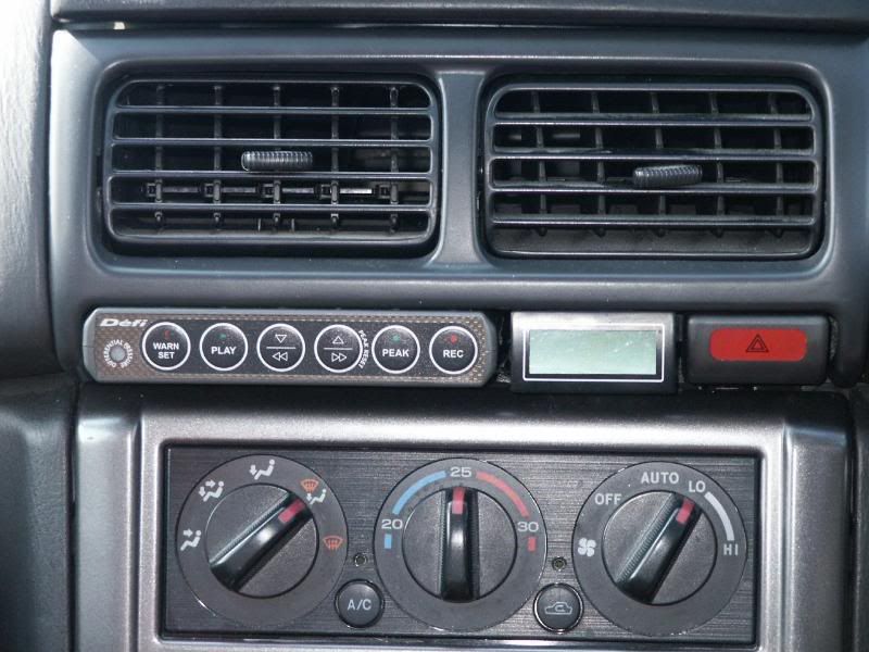
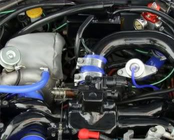
ACT's - anyone monitor theirs?
#31
now a Hybrid GT2 FMIC, fitted at Harveys during the rebuild.
To start with, yes, then it dropped, but only to around 40 degrees.
Nope, it's on my "to do" list, the bonnet seal has been altered at the o/s front to allow more cold air in. I will have a go at shielding it with alloy plate when I get back from France in September.
To start with, yes, then it dropped, but only to around 40 degrees.
Nope, it's on my "to do" list, the bonnet seal has been altered at the o/s front to allow more cold air in. I will have a go at shielding it with alloy plate when I get back from France in September.
I think this will not be insignificant to air intake across the induction area
#32
Jeff :
Aluminium is an exceptionally good heat conductor. Give me a ring when you get home and when you know the size of sheet you require. I will see if I can sort out a section of carbon fibre and heat mat. Best to do this in cardboard as a template until you get the shape and holes in the right place. Run it from the driver side chassis rail to the bonnet and avoid gaps where you could get hot engine bay air ingress. It can be topped off with door seal rubber or similar to form a seal to the underside of the bonnet.
Nope, it's on my "to do" list, the bonnet seal has been altered at the o/s front to allow more cold air in. I will have a go at shielding it with alloy plate when I get back from France in September.
#33
Air intake temperature will have little effect on the ACT if the intercooler is capable of doing its job properly. It can however have an influence on power delivered because the colder/denser the charge the more power can be developed.
Every 10C ACT is 2-4% BHP.
Monitoring ACTs will quickly show the defficiencies of the TMIC as opposed to an efficient FMIC.
Do not place the sensor in the inlet manifold as it will possibly measure the temperature of the cast manifold or be influenced by it. On an FMIC I measure the ACT with the probe in the hard pipe just before the throttle body. On a TMIC I insert the probe in an aluminium coupler inserted in the pipe between the TMIC and TB but not in contact with either.
ACTs below ambient may be as a result of disparity of guages used.
450 bhp 2 litre with Hybrid GT FMIC. Cruise is typically 2-4C over ambient.
Typical rolling road Power run 15C over ambient.
Fast cross country, never more than 15C over ambient and typicall 10-12C.
Top speed run, 160-170mph, up to 20C over.
EGTs run to 900-930C max and I never take it beyond 930C.
EGTs with water methanol injection around 800C or just over.
EGTs with 20% methanol only, up to 850-860C.
335 bhp STi 3 Wagon. O/E TMIC and turbo. Sprint 0-100 mph ACT exceeding scale at 70C so beyond 50C over ambient.
Same car 392 bhp with STi 8 TMIC and bigger turbo injectors etc. Bigger bonnet scoop and STi 8 under tray. Fast cross country. Typically 25-30C over ambient.
RR power run, typically 25-35C over ambient.
#35
Quote Harvey
" On a TMIC I insert the probe in an aluminium coupler inserted in the pipe between the TMIC and TB but not in contact with either".
Is this something you've made yourself?
Is the probe permanently in the pipe?
I'd be interested in doing this but want to make sure it seals properly.
Is the throttle body coolant delete mod worth doing?
Last edited by Rescue Dude; 10 August 2011 at 05:33 PM.
#36
My sensor is screwed in the intercooler and clearly reads end tank temp and not the actual air charge temp especially after a hot start up! But it does stabilise after a ver short run. Prehaps I can insulate it? A plastic screw in boss maybe the answer
#37
Quote Harvey
" On a TMIC I insert the probe in an aluminium coupler inserted in the pipe between the TMIC and TB but not in contact with either".
Is this something you've made yourself?
Is the probe permanently in the pipe?
I'd be interested in doing this but want to make sure it seals properly.
Is the throttle body coolant delete mod worth doing?
" On a TMIC I insert the probe in an aluminium coupler inserted in the pipe between the TMIC and TB but not in contact with either".
Is this something you've made yourself?
Is the probe permanently in the pipe?
I'd be interested in doing this but want to make sure it seals properly.
Is the throttle body coolant delete mod worth doing?
2. Yes.
3. Done properly there is no reason it would not seal.
4. Yes. Every little bit counts.
My sensor is screwed in the intercooler and clearly reads end tank temp and not the actual air charge temp especially after a hot start up! But it does stabilise after a ver short run. Prehaps I can insulate it? A plastic screw in boss maybe the answer
#38
1. I simply cut a piece of aluminium pipe of the appropriate diameter but a number of the silicon hose suppliers will also sell you joiners which do the job. Simply drill and tap.
2. Yes.
3. Done properly there is no reason it would not seal.
4. Yes. Every little bit counts.
The real solution would be to mount it between the throttle body and TMIC output. Where it is at present the sensor is most likely influenced by the engine bay heat radiating in to the sides of the TMIC.
2. Yes.
3. Done properly there is no reason it would not seal.
4. Yes. Every little bit counts.
The real solution would be to mount it between the throttle body and TMIC output. Where it is at present the sensor is most likely influenced by the engine bay heat radiating in to the sides of the TMIC.
http://www.viperperformance.co.uk/pr...php?xscId=9822
#39
I'll look into it as I def needs addressed as it is causing running problems when left after running
#40
I have altered mine too - removed the rubber strip and unscrewed the stop blobk to lift the shut position...
https://lh3.googleusercontent.com/-2...0/P1010254.JPG
I think this will not be insignificant to air intake across the induction area
https://lh3.googleusercontent.com/-2...0/P1010254.JPG
I think this will not be insignificant to air intake across the induction area
#41
Here's the working pic link (post #31 above): https://lh3.googleusercontent.com/-2...0/P1010254.JPG
#42


To mount the probe I drill and tap the hard pipe of the FMIC just before the throttle body. On a TMIC I simply cut a ring of stainless or aluminium pipe, insert it in the rubber joiner between the TMIC and throttle body, ensure it will not touch either of these and then drill and tap with a small hole cut through the rubber.
Last edited by harvey; 14 August 2011 at 03:19 PM.
#43
I have one of Harveys dual sensor gauges (same as above) and they are very very nice indeed.
one sensor is just before the tb in the fmic pipe, and the other is in the pipe that my air filter attaches to in the front bumper.


one sensor is just before the tb in the fmic pipe, and the other is in the pipe that my air filter attaches to in the front bumper.


Thread
Thread Starter
Forum
Replies
Last Post
Sam Witwicky
Engine Management and ECU Remapping
17
13 November 2015 11:49 AM
Mister:E
Subaru Parts
2
24 September 2015 02:37 PM


