Is there any harm in changing a FMIC to run clockwises?
#1
How all,
I'm looking into various ways of reduce lag on my car, mapping, different spec turbo, headers and so on, but thats not the point of this thread.
I was looking at the pipwork for my FMIC today and began to wonder would there be any harm in changing the way the charged air runs through it? Changing it from anticlockwise to clockwise?
My reason for think this is, on a standard turbo the exit point facing into the engine bay, and so the FMIC pipework has to do a 180 turn heading over to the off-side wing. IMHO this has to disturb the air flow and clearly increases the lengh of the pipework.

My thinking is I could simply create a pipe that goes from the turbo exit to the near side wing, thus eliminating the 180 bend and reducing the pipework.
I'd then move the cooled charged air pipe to the off side, and clearly move the mount for the D/V too.
On its own I know this would make little to no difference but I'm thinking big picture, mixing it with a host of other mods and changes to the engine bay and the way the pipework is laid out.
I've seen people tackle this another way by rotate the turbine housing on the turbo, but I didn't want to go this route as I can't be dealing with the clearence issue that are associated with it, plus I don't fancy messing about the new turbo I've got, thats just asking for something to go wrong.
I'm looking into various ways of reduce lag on my car, mapping, different spec turbo, headers and so on, but thats not the point of this thread.
I was looking at the pipwork for my FMIC today and began to wonder would there be any harm in changing the way the charged air runs through it? Changing it from anticlockwise to clockwise?
My reason for think this is, on a standard turbo the exit point facing into the engine bay, and so the FMIC pipework has to do a 180 turn heading over to the off-side wing. IMHO this has to disturb the air flow and clearly increases the lengh of the pipework.

My thinking is I could simply create a pipe that goes from the turbo exit to the near side wing, thus eliminating the 180 bend and reducing the pipework.
I'd then move the cooled charged air pipe to the off side, and clearly move the mount for the D/V too.
On its own I know this would make little to no difference but I'm thinking big picture, mixing it with a host of other mods and changes to the engine bay and the way the pipework is laid out.
I've seen people tackle this another way by rotate the turbine housing on the turbo, but I didn't want to go this route as I can't be dealing with the clearence issue that are associated with it, plus I don't fancy messing about the new turbo I've got, thats just asking for something to go wrong.
#2
Scooby Senior
iTrader: (3)
Joined: Jun 2006
Posts: 14,333
Likes: 0
From: Slowly rebuilding the kit of bits into a car...
If you generally drive South, then anti-clockwise is best.... 
Due to the Coriolis effect !
Seriously, as you know, the shorter the better....
dunx
P.S. I'm NOT willing to sacrifice the P.S. or the aircon myself !

Due to the Coriolis effect !
Seriously, as you know, the shorter the better....
dunx
P.S. I'm NOT willing to sacrifice the P.S. or the aircon myself !
Last edited by dunx; 10 June 2009 at 02:30 PM.
#3
I would imagine which ever way the air flows thru the intercooler doesn't matter as there are no one way valves in the system. I think some ppl have also reversed the way the inlet manifold sits to also reduce pipe work length but how you get round the alternator I dont know.
#4
I would imagine which ever way the air flows thru the intercooler doesn't matter as there are no one way valves in the system. I think some ppl have also reversed the way the inlet manifold sits to also reduce pipe work length but how you get round the alternator I dont know.
But the cost of this and the benifits don't make it worth my while, plus I like my air con to much.
I'm thinking at the moment of flipping the intercooler and my above suggested mod to reduce the pipework length.
#6
#7
You would have to think of a way of reflecting/sheilding the cooled air from the turbo as it looks thike your method is going to direct the pipework right back over the turbo heating the air you have just cooled.
Trending Topics
#8
Good point, I've just bought a Turbo jacket though so that will help with that. Plus once I've sorted my pipework out I'm going to exhaust wrap the hot pipe and reflective wrap the cool pipe.
#9
My Hybrid FMIC runs clockwise on my newage without clashing with AC or power steering.
I have had to change the battery to a small sealed unit though.
I have had to change the battery to a small sealed unit though.
Last edited by jd5217; 11 June 2009 at 02:27 PM.
#10
Sponsor
iTrader: (250)
Joined: Jul 2008
Posts: 11,933
Likes: 21
From: 2minutes from J10 M6 Walsall West Midlands
i have been there and done this i didnt see no difference in just changing air flow anticlockwise too clockwise
but then
i did the job the way i should have in the first place and rotated the inlet manifold/flipped the intercooler/rotated the turbo housing and got the pipe work down from nearly 15ft long to under 5ft and all this made a hugh difference and makes it a complete different car to drive here few pics too get the idea


all this cost me pennies too do as i did it myself and had all the pipe work off the front mount already so used what i needed and with the extra i made a inner wing mounted air filter kit which worked nicely too..
i did use a tdo5 turbo orignally to rotate the housing which was a pain todo as had to cut 90 elbow off and there is a locating dowel that needs cutting off aswell to actually rotate the housing and once i did that i had to make a new actuator bracket to get it all to work but it is possable im now using a power enterprise pe18/20 hybrid turbo which is a vf 22 casing turbo and the housing is so simple to rotate and actuator bracket just bolts back on as it normally would...i know all this isnt what you wanted to know but thought id show you another way than the normal route lol hope it helps
but then
i did the job the way i should have in the first place and rotated the inlet manifold/flipped the intercooler/rotated the turbo housing and got the pipe work down from nearly 15ft long to under 5ft and all this made a hugh difference and makes it a complete different car to drive here few pics too get the idea


all this cost me pennies too do as i did it myself and had all the pipe work off the front mount already so used what i needed and with the extra i made a inner wing mounted air filter kit which worked nicely too..
i did use a tdo5 turbo orignally to rotate the housing which was a pain todo as had to cut 90 elbow off and there is a locating dowel that needs cutting off aswell to actually rotate the housing and once i did that i had to make a new actuator bracket to get it all to work but it is possable im now using a power enterprise pe18/20 hybrid turbo which is a vf 22 casing turbo and the housing is so simple to rotate and actuator bracket just bolts back on as it normally would...i know all this isnt what you wanted to know but thought id show you another way than the normal route lol hope it helps
#11
Thats exactly what I'm after, I did have another thread running about how to flip mount the intercooler too, so thats helped. Where did you cut to get the pipes through? Did it effect the strengh of the front cross member?
#12
Sponsor
iTrader: (250)
Joined: Jul 2008
Posts: 11,933
Likes: 21
From: 2minutes from J10 M6 Walsall West Midlands
if u remove ur head lights just under them u see a thin piece ov sheet metal thats where u cut and u cut it down too the main part ov the cross menber if that makes sense ur only cutting very thin sheet steel so no structral changes so no strengh is lost the measurements where to cut will change pending on the bends ands intercooler type you have best thing todo is get intercooler in place and go from theree its actually really simple todo and helps so much
Last edited by Mattybr5@MB Developments; 11 June 2009 at 05:01 PM.
#13
if u remove ur head lights just under them u see a thin piece ov sheet metal thats where u cut and u cut it down too the main part ov the cross menber if that makes sense ur only cutting very thin sheet steel so no structral changes so no strengh is lost the measurements where to cut will change pending on the bends ands intercooler type you have best thing todo is get intercooler in place and go from theree its actually really simple todo and helps so much
#14
Right got four days off gonna give it a go. I've got the headlights etc all off, just need to get the bumper off now. Typical its started to rain, hopfully it will stop in a moment.
Matty, where do you take the pipe work on the near side. I'm struggling to see where I can take the pipework. I'm think I can move the horn to get a little bit more room, other than that its move the battery, but I don'tthink I need to do that as from your pictures you didn't have to.
Matty, where do you take the pipe work on the near side. I'm struggling to see where I can take the pipework. I'm think I can move the horn to get a little bit more room, other than that its move the battery, but I don'tthink I need to do that as from your pictures you didn't have to.
#17
I have done this as well and brought the pipes up under the headlights which is the easiest way to get them into the engine bay, it does reduce the pipework length. I will reduce mine again if I go to a rotated turbo set up next year.
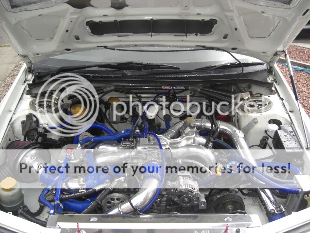
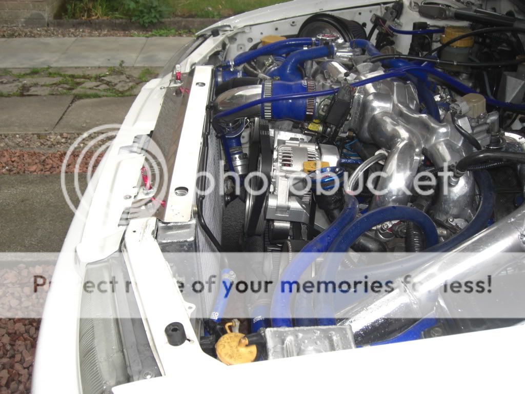
Some more pics on my project thread, depending on boost level its not a good idea to rely on samco and clamps to hold the pipe work together. Each join should have a proper beaded end or better still get it welded up like I did and have beaded ends where any joins are that way you wont have pipes blowing off under boost.
Some more pics here
https://www.scoobynet.com/projects-4...ntually-3.html
#18
your car is just different. lol. (in a good way)
so much has changed its a no wonder you can run it that way. no fans. alternator moved, now aircon, abs master cylinder isnt where mine is, your battery is in boot. wrong way inlet. the list goes on.
looks really nice mate
so much has changed its a no wonder you can run it that way. no fans. alternator moved, now aircon, abs master cylinder isnt where mine is, your battery is in boot. wrong way inlet. the list goes on.
looks really nice mate
#19
 But I do have the battery in the engine bay its a gel battery mounted on the passengers side chassis leg next to strut turret you can just see the orange top of it. I also have 2 fans mounted between the radiator and the intercooler and aircon god I live in Scotland why would I need aircon
I know what you mean tho it makes it easier without all the add ons that make a road car pleasant to drive.
You can still take the intercooler pipes under the head lights and then run them the standard route through the engine bay but it is marginal if it is worth the hassle.
Fitting a remote steering pump is a doddle. Get a hold of a newage pump and bracket, top tip make sure you get the bracket to fit the pump as the hole spacing for the pumps changed around the bugeye to blobeye period and are different to the classic brackets, I know coz I now have 3 brackets

Also get the remote resevoir and mounting bracket and all the pipe work from the steering rack to remote resevoir and to the pump. I took the pressure hose from the pump to the rack to my local pirtek and had a flexi hose swagged on so that I could route the section from the pump down to the inner wing the way I wanted it. Total cost under £100

Last edited by Arch; 24 July 2009 at 01:38 PM. Reason: wish I could spell
#20
well impressed mate. i did this type of thing to my old ibiza. ripped apart and started removing things that wasnt wanted and battery in boot, air con gone. it does make alot of room
#22
Rotating the turbo , or clocking the housing??.
Rotating the turbo would require custom up and downpipes, clocking the turbo(so the pressure side is not top right, but down left) only requires a new wastegate mounting bracket, or an EWG.
Been looking into the latter myself. as that way I can run just 1 90 degree bend, and a straight length of pipe on the hotside, and use another short pipe for the coldside.
I have already reversed the manifold and IC core, this seems to be the last step , and allowes for the shortest piping set on a fmic.
I am running a td05-18G in stock position,and run the hotside down the (on my car) drivers side, and the coldside right beind the radiator to the TB.
This already saved much pipework , but clocking the turbo would reduce the total amount of piping to a maximum of 4 feet.
Some pictures (MAF is going to be ditched, swapping the PowerFC for a Syvecs)
Total shot of engine bay and piping.
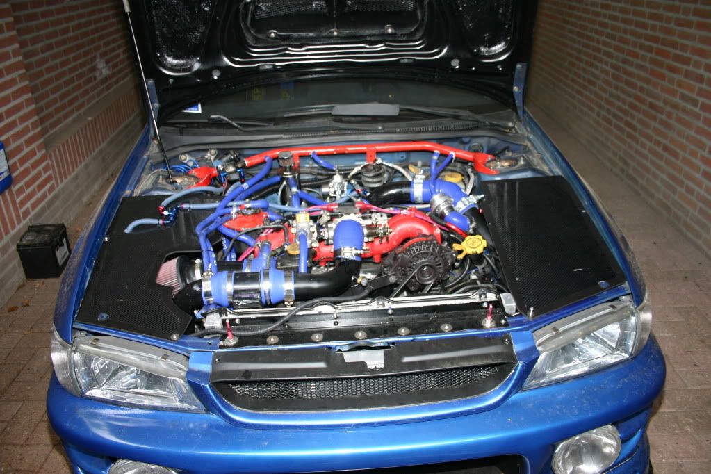
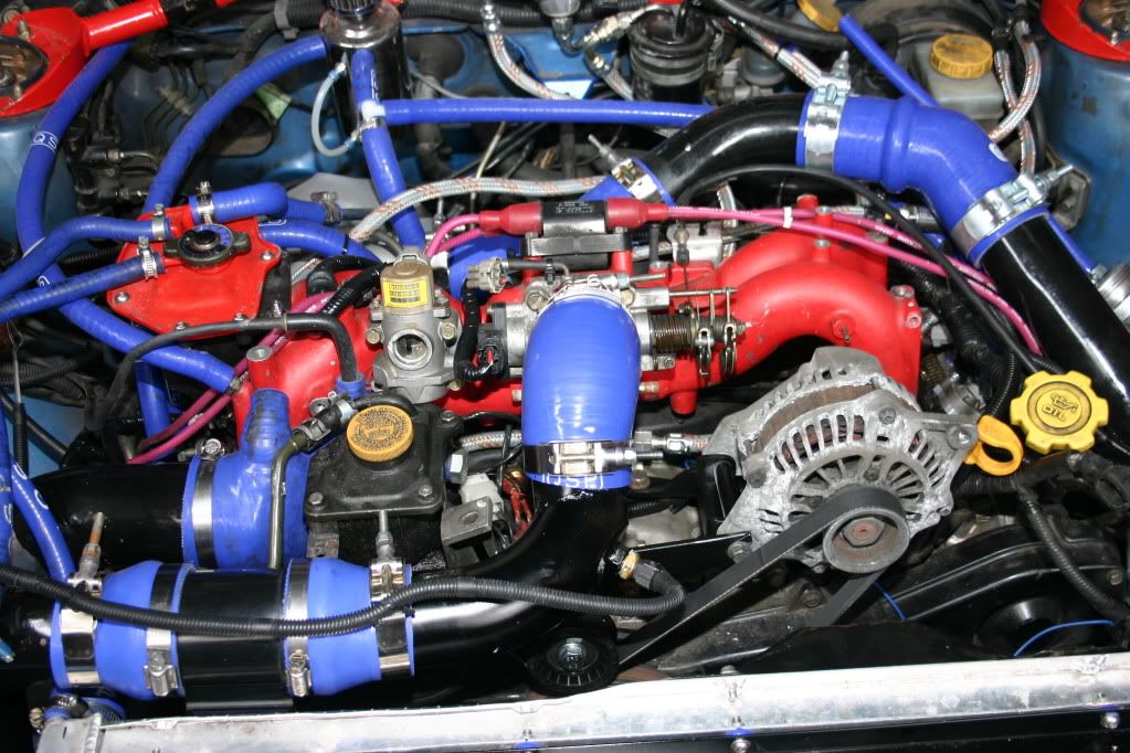
Flipped the IC core, and removed sheetmetal for piping to run through.
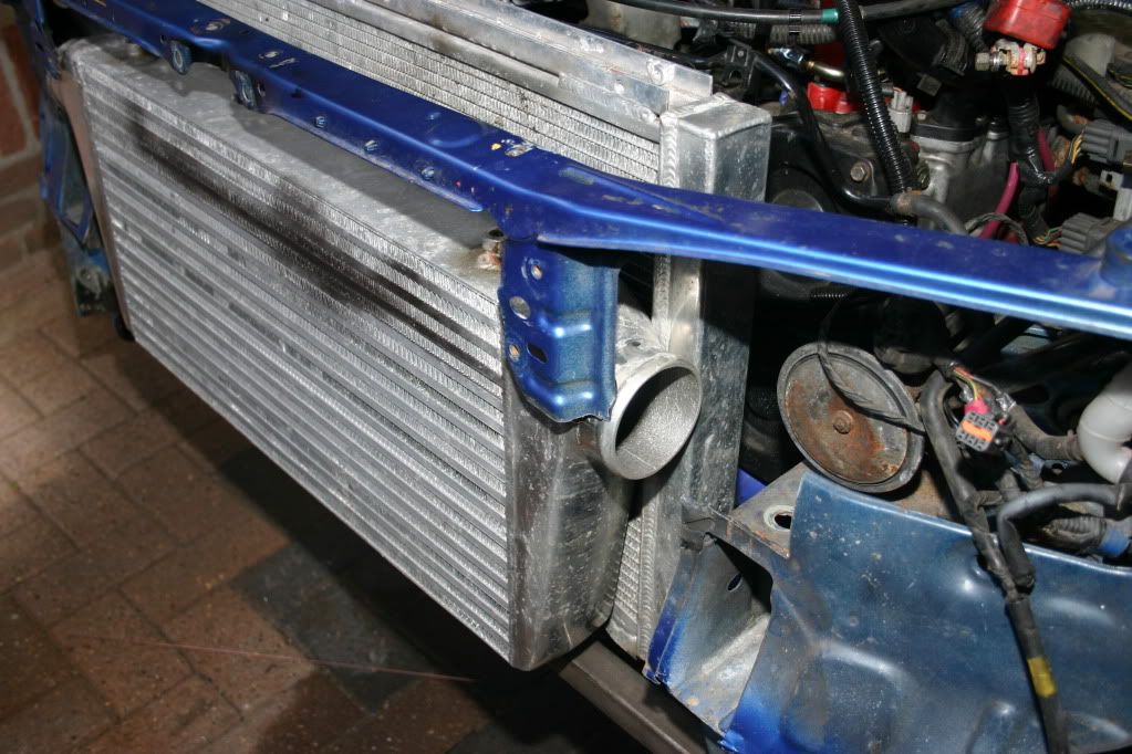
Rotating the turbo would require custom up and downpipes, clocking the turbo(so the pressure side is not top right, but down left) only requires a new wastegate mounting bracket, or an EWG.
Been looking into the latter myself. as that way I can run just 1 90 degree bend, and a straight length of pipe on the hotside, and use another short pipe for the coldside.
I have already reversed the manifold and IC core, this seems to be the last step , and allowes for the shortest piping set on a fmic.
I am running a td05-18G in stock position,and run the hotside down the (on my car) drivers side, and the coldside right beind the radiator to the TB.
This already saved much pipework , but clocking the turbo would reduce the total amount of piping to a maximum of 4 feet.
Some pictures (MAF is going to be ditched, swapping the PowerFC for a Syvecs)
Total shot of engine bay and piping.


Flipped the IC core, and removed sheetmetal for piping to run through.

#24
Scooby Regular
iTrader: (18)
Joined: May 2006
Posts: 3,420
Likes: 2
From: Middx / Herts / Bucks / Essex
I've got a TD05 18G supplied and fitted by Harvey and had it clocked right the way round to reduce the piping and increase smoother gass flow around the fmic.
Idealy I'd like to get a reverse inlet, but I cant live without air con so thats not gonna happen... I also wouldnt be able to relocate my power steering res as I've got the ABS occupying that position you've used Arch. Altho I'm toying with the idea of removing the ABS all 2gether as I hear only good things about running without it...
Over the other side I've got an oil catch can and have relocated my battery and washer bottle to the boot.
Sorry I havnt got any pics guys, I'm in the process of finishing off bits and bobs under my bonnet and when I'm done I'll post up a few pics

#25
i'll stick with the top mount good for 400 and lag is nothing i have to worry about, i think front mounts are great but are for show, if they really needed 1 then subaru would have designed the engine to have 1, don't you think?
#26
Scooby Regular
iTrader: (18)
Joined: May 2006
Posts: 3,420
Likes: 2
From: Middx / Herts / Bucks / Essex
In a way I agree that if the car 'really' needed it then Subaru would have incorporated a fmic in the design, but I disagree with you in that you will achieve more cooling from the application of a fmic.
An STi tmic has been proven to be sufficient in sustaining 400bhp, but if you're running such high power, wouldnt you want to do everything you could to ensure that the air entering the engine is a cool as possible for maximum efficiency?
The differentail between tmic and fmic lag is minimal and there are many other measures which can be taken to reduce that differential even further.
#28
How all,
I'm looking into various ways of reduce lag on my car, mapping, different spec turbo, headers and so on, but thats not the point of this thread.
I was looking at the pipwork for my FMIC today and began to wonder would there be any harm in changing the way the charged air runs through it? Changing it from anticlockwise to clockwise?
My reason for think this is, on a standard turbo the exit point facing into the engine bay, and so the FMIC pipework has to do a 180 turn heading over to the off-side wing. IMHO this has to disturb the air flow and clearly increases the lengh of the pipework.

My thinking is I could simply create a pipe that goes from the turbo exit to the near side wing, thus eliminating the 180 bend and reducing the pipework.
I'd then move the cooled charged air pipe to the off side, and clearly move the mount for the D/V too.
On its own I know this would make little to no difference but I'm thinking big picture, mixing it with a host of other mods and changes to the engine bay and the way the pipework is laid out.
I've seen people tackle this another way by rotate the turbine housing on the turbo, but I didn't want to go this route as I can't be dealing with the clearence issue that are associated with it, plus I don't fancy messing about the new turbo I've got, thats just asking for something to go wrong.
I'm looking into various ways of reduce lag on my car, mapping, different spec turbo, headers and so on, but thats not the point of this thread.
I was looking at the pipwork for my FMIC today and began to wonder would there be any harm in changing the way the charged air runs through it? Changing it from anticlockwise to clockwise?
My reason for think this is, on a standard turbo the exit point facing into the engine bay, and so the FMIC pipework has to do a 180 turn heading over to the off-side wing. IMHO this has to disturb the air flow and clearly increases the lengh of the pipework.

My thinking is I could simply create a pipe that goes from the turbo exit to the near side wing, thus eliminating the 180 bend and reducing the pipework.
I'd then move the cooled charged air pipe to the off side, and clearly move the mount for the D/V too.
On its own I know this would make little to no difference but I'm thinking big picture, mixing it with a host of other mods and changes to the engine bay and the way the pipework is laid out.
I've seen people tackle this another way by rotate the turbine housing on the turbo, but I didn't want to go this route as I can't be dealing with the clearence issue that are associated with it, plus I don't fancy messing about the new turbo I've got, thats just asking for something to go wrong.
2) The easiest way to remove the 180 degree bend on the hot pipe is to clock the turbo so the compressor outlet is at 180 degrees to what it was before. You need good workshop facility and knowledge to do this without distorting the compressor housing when aluminium welding a new lug in position to take the relocated WG Actuator mounting bracket.
3) The benefit from clocking as above is probably so small it cannot be measured by the bum dyno but many little things will add up to some benefit. Only you know if the investment in time or money is worth it and for some people there is the feel good factor of being different or a placebo effect.
Similarly reversing the inlet manifold to shorten the FMIC pipe run is a lot of work and in my experience any gain is so small it is not signifigant. The usual cause of lag on a well designed FMIC are usually attributable to other factors and I have demonstarted this on a number of occasions but the myth of lag continues either that or there are a lot of badly designed FMIC systems out there.
#29
The air out of the turbo compressor can be up to 200C on hard boost and therefore higher than the ambient air in the area of the hot pipe, especially if you have the exhaust housing wrapped. Therefore wrapping the hot pipe is a retrograde step as the air contained will already be loosing heat on its way to the core.
Exhaust heat wrapping the exit pipe from the core to the throttlebody is a good idea and on top of the exhaust wrap you can add a reflective sleeve from the likes of Nimbus.
#30
An STi tmic has been proven to be sufficient in sustaining 400bhp,
You do not suddenly arrive at a particular power figure and hit a brick wall. As ACTs increase power reduces to the point it tails off substantially.
In one well documented case I had 392 bhp on an STi 8 TMIC and the only change was to a Hybrid GT FMIC. On the same rollers the next power runs were 401 bhp before remapping where we had 410 bhp.
Incidentally, spool to 1 bar was exactly the same on the graphs.
but if you're running such high power, wouldnt you want to do everything you could to ensure that the air entering the engine is a cool as possible for maximum efficiency?
The differentail between tmic and fmic lag is minimal and there are many other measures which can be taken to reduce that differential even further.


