
Fitting Prosport Steppers Monday
 14 January 2012, 09:01 PM
#1
Scooby Regular
Thread Starter
iTrader: (1)

Join Date: Dec 2011
Location: Wolverhampton
Posts: 144
Likes: 0
Received 0 Likes
on
0 Posts
Hi All,
I've got all my tools together now and going to fit these gauges on Monday.
I've got a 07 Hawk wrx and a couple of last minute questions
Is the wiring for the clock sufficient to wire in 3 gauges?
Perm Live
Acc Live
Ground
Illum
Has anyone got a pic of where i sould t in for the boost?
Wish me Luck
Thanks for any replies
 14 January 2012, 09:10 PM
#2
Scooby Regular
iTrader: (40)

Join Date: Aug 2008
Location: Suffolk
Posts: 2,163
Likes: 0
Received 0 Likes
on
0 Posts
Hi All,
I've got all my tools together now and going to fit these gauges on Monday.
I've got a 07 Hawk wrx and a couple of last minute questions
Is the wiring for the clock sufficient to wire in 3 gauges?
Perm Live
Acc Live
Ground
Illum
Has anyone got a pic of where i sould t in for the boost?
Wish me Luck
Thanks for any replies
I've got all my tools together now and going to fit these gauges on Monday.
I've got a 07 Hawk wrx and a couple of last minute questions
Is the wiring for the clock sufficient to wire in 3 gauges?
Perm Live
Acc Live
Ground
Illum
Has anyone got a pic of where i sould t in for the boost?
Wish me Luck
Thanks for any replies
You can cut the t piece anywhere on the smaller pipe that goes to the dump valve
14 January 2012, 10:55 PM
#7
Scooby Regular
Thread Starter
iTrader: (1)
Join Date: Dec 2011
Location: Wolverhampton
Posts: 144
Likes: 0
Received 0 Likes
on
0 Posts
I've just been browsing and its the pipe that is visible that comes off to the right? the T piece that you have with the gauges fit ok?
When you wired to the clock did you piggy back from gauge to gauge, with 1 set of wires connecting to the clock loom?
Sorry for all the Q's just want to make sure i don't **** it up!
When you wired to the clock did you piggy back from gauge to gauge, with 1 set of wires connecting to the clock loom?
Sorry for all the Q's just want to make sure i don't **** it up!
Trending Topics
14 January 2012, 11:07 PM
#8
Scooby Regular
iTrader: (4)
Join Date: Apr 2007
Location: Northants
Posts: 186
Likes: 0
Received 0 Likes
on
0 Posts
I've just been browsing and its the pipe that is visible that comes off to the right? the T piece that you have with the gauges fit ok?
When you wired to the clock did you piggy back from gauge to gauge, with 1 set of wires connecting to the clock loom?
Sorry for all the Q's just want to make sure i don't **** it up!
When you wired to the clock did you piggy back from gauge to gauge, with 1 set of wires connecting to the clock loom?
Sorry for all the Q's just want to make sure i don't **** it up!
there easy to do mate !! take your time and be methodical....
the herdest bit is the oil temp sensor above cylinder 3 make sure you use a quality hex bit or allen key as it is tight....... ill put some piccys on for you tommorow if you need them..
15 January 2012, 01:50 PM
#10
Scooby Regular
iTrader: (4)
Join Date: Apr 2007
Location: Northants
Posts: 186
Likes: 0
Received 0 Likes
on
0 Posts
hi mate some piccys of installation on a hawkeye
[IMG]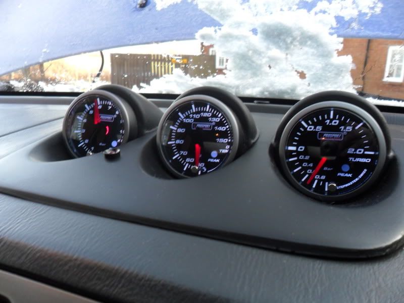 [/IMG]
[IMG] [/IMG]
[IMG] [/IMG]
[IMG] [/IMG]
[IMG] [/IMG]
the last piccy is where the temp gauge goes!! you need to remove the intercooler and hold back or remove the recirc pipe that goes to the inlet pipe to gain access (its fiddly)
any more questions please ask
[IMG]
[/IMG][IMG]
[/IMG][IMG]
[/IMG][IMG]
[/IMG][IMG]
[/IMG]the last piccy is where the temp gauge goes!! you need to remove the intercooler and hold back or remove the recirc pipe that goes to the inlet pipe to gain access (its fiddly)
any more questions please ask
Last edited by Wilky0302; 15 January 2012 at 01:51 PM.
15 January 2012, 07:08 PM
#11
Scooby Regular
Thread Starter
iTrader: (1)
Join Date: Dec 2011
Location: Wolverhampton
Posts: 144
Likes: 0
Received 0 Likes
on
0 Posts
Hi Wilky thanks for the pics mate,
The existing oil pressure sensor did you reconnect it? because it looks like a loop in the wire?
Did you use ptfe tape on the senders?
Have you got a pic of where you fitted the boost to the dump valve?
Cheers mate
The existing oil pressure sensor did you reconnect it? because it looks like a loop in the wire?
Did you use ptfe tape on the senders?
Have you got a pic of where you fitted the boost to the dump valve?
Cheers mate
15 January 2012, 08:36 PM
#12
Scooby Regular
iTrader: (4)
Join Date: Apr 2007
Location: Northants
Posts: 186
Likes: 0
Received 0 Likes
on
0 Posts
hi
yes the sensor is reconnected with a piece of wire spliced into the original loom!
[IMG] [/IMG]
the pic is where the boost gauge fits to the dump valve attaches
below is a pic of where i put the boost gauge sensor it is next to the boost control solenoid
[IMG][/IMG]
yes the sensor is reconnected with a piece of wire spliced into the original loom!
[IMG]
[/IMG]the pic is where the boost gauge fits to the dump valve attaches
below is a pic of where i put the boost gauge sensor it is next to the boost control solenoid
[IMG]
[/IMG]
15 January 2012, 10:31 PM
#14
Scooby Regular
Thread Starter
iTrader: (1)
Join Date: Dec 2011
Location: Wolverhampton
Posts: 144
Likes: 0
Received 0 Likes
on
0 Posts
Wilky Thanks for your help, i'm greatful and it makes it abit clearer!!!! I'm stil a little mythed about the t in on the boost, my t piece doesn't look big enough? it's the original with the gauge.
Just one other thing did you daisy chain the power/ground etc...... to the gauges using the cables and splice in with one?
Just one other thing did you daisy chain the power/ground etc...... to the gauges using the cables and splice in with one?
15 January 2012, 10:45 PM
#15
Scooby Regular
iTrader: (4)
Join Date: Apr 2007
Location: Northants
Posts: 186
Likes: 0
Received 0 Likes
on
0 Posts
Wilky Thanks for your help, i'm greatful and it makes it abit clearer!!!! I'm stil a little mythed about the t in on the boost, my t piece doesn't look big enough? it's the original with the gauge.
Just one other thing did you daisy chain the power/ground etc...... to the gauges using the cables and splice in with one?
Just one other thing did you daisy chain the power/ground etc...... to the gauges using the cables and splice in with one?
I individually wired each gauge.. so what i did was removed the clock and put a multi wiring plug on the end of each wire then i wired each gauge to each connector... on the back of the clock it tells you which wire does what 12v earth etc..... the hardest bits of the installl were
1) oil temp cylinder 3
2) finding somewhere in the bulk head to get the cabling through
after that it was pretty straight forward.... it will take you the best part of a day if you havent done them before
Also be aware dont tighten the gauge adapters too tight as they will snap
any probs come back to me
15 January 2012, 11:03 PM
#16
Scooby Regular
Thread Starter
iTrader: (1)
Join Date: Dec 2011
Location: Wolverhampton
Posts: 144
Likes: 0
Received 0 Likes
on
0 Posts
ok wilky, have you heard of anyone daisy chaining them?
i'll be taking it steady mate i've got a few days to complete, which grommet did you use to get through the bulkhead?
i'll be taking it steady mate i've got a few days to complete, which grommet did you use to get through the bulkhead?

 16 January 2012, 03:50 PM
#20
Scooby Regular
Thread Starter
iTrader: (1)
Join Date: Dec 2011
Location: Wolverhampton
Posts: 144
Likes: 0
Received 0 Likes
on
0 Posts
Hi Wilky, i've got the boost functioning, it's reading the same as yours do you need to have the gauge set up? so it's reading closer to 0? i have noticed a tiny allen key screw in the back of the gauge?

Thread
Thread Starter
Forum
Replies
Last Post
JonMc
Subaru Parts
22
06 February 2016 09:50 PM
oilman
Trader Announcements
15
01 October 2015 11:55 AM
matt12
Engine Management and ECU Remapping
4
14 September 2015 09:36 AM