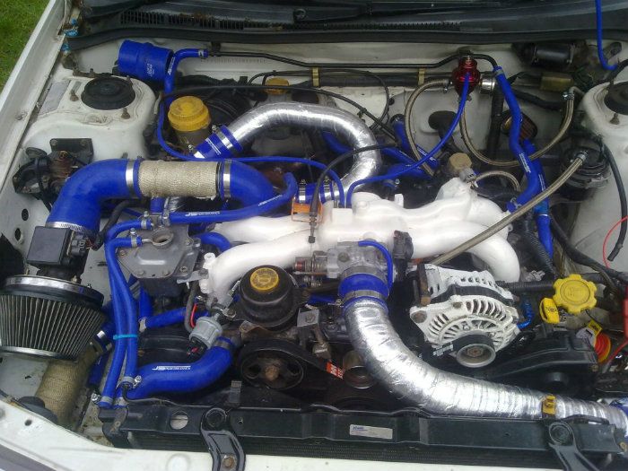
classic reverse inlet
#1
Well i decided to do mine although its been said its not worth the hassle but they do look trick when done.
i did contemplate just spinning it and either using a wedge on the housing or a 45 degree hose but decided if i was going to it i'd do it right.
I took a few pics as went along and will explain what i did so anyone wishing to do one has a rough guide.
Firstly remove manifold, if unsure on this a guide can be found here https://www.scoobynet.com/technical-...-guide-up.html
it might not be for same inlet but the basics are the same.
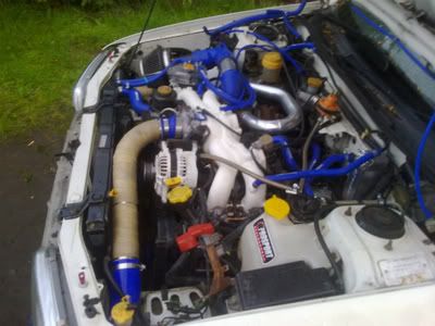
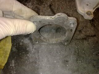
with the inlet on the bench all stripped down i cut the plate the throttle body bolts to off and cleaned the plate up as this was to be reused. see below pics
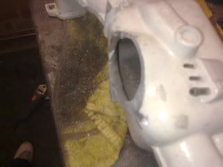
I then cut a hole in the centre of the front of manifold can't remember the exact size but will check tomorrow.
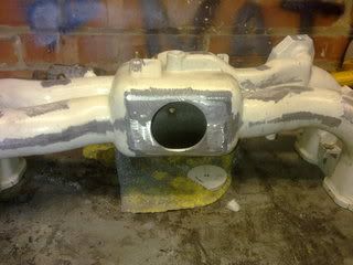
i then dropped the manifold off at a local fabrication firm for them to weld a plate to the rear where the throttle body was originally and to weld the plate to the front of inlet.
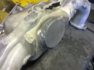
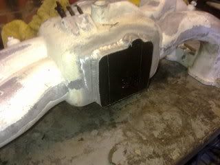
as i was having the inlet painted i decided to remove all unwanted mounting lugs and flat off the casting marks.
picked up inlet from painters today and started refitting parts
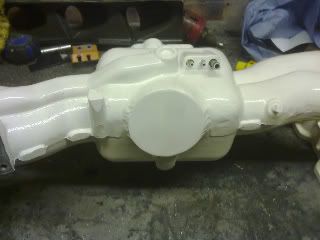
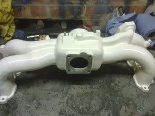
trial fitted
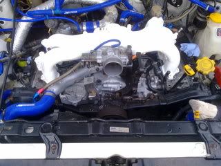
as i progress more i will tell of any problems i came across and the solutions.
i did contemplate just spinning it and either using a wedge on the housing or a 45 degree hose but decided if i was going to it i'd do it right.
I took a few pics as went along and will explain what i did so anyone wishing to do one has a rough guide.
Firstly remove manifold, if unsure on this a guide can be found here https://www.scoobynet.com/technical-...-guide-up.html
it might not be for same inlet but the basics are the same.
with the inlet on the bench all stripped down i cut the plate the throttle body bolts to off and cleaned the plate up as this was to be reused. see below pics


I then cut a hole in the centre of the front of manifold can't remember the exact size but will check tomorrow.

i then dropped the manifold off at a local fabrication firm for them to weld a plate to the rear where the throttle body was originally and to weld the plate to the front of inlet.


as i was having the inlet painted i decided to remove all unwanted mounting lugs and flat off the casting marks.
picked up inlet from painters today and started refitting parts


trial fitted

as i progress more i will tell of any problems i came across and the solutions.
#3
looks good that. so far only problem i can see is sorting the throttle cable linkage etc out. The cars been off road 16 months and we've got the mrs uk2000 to drive about in so i thought whats a few more weeks gona hurt. i also plan on flipping the front mount, moving the battery and the washer bottle to the boot, and mounting the fuse box through into the wing and the boost solenoid, air filter etc into other wing behind a removable cover,
#4
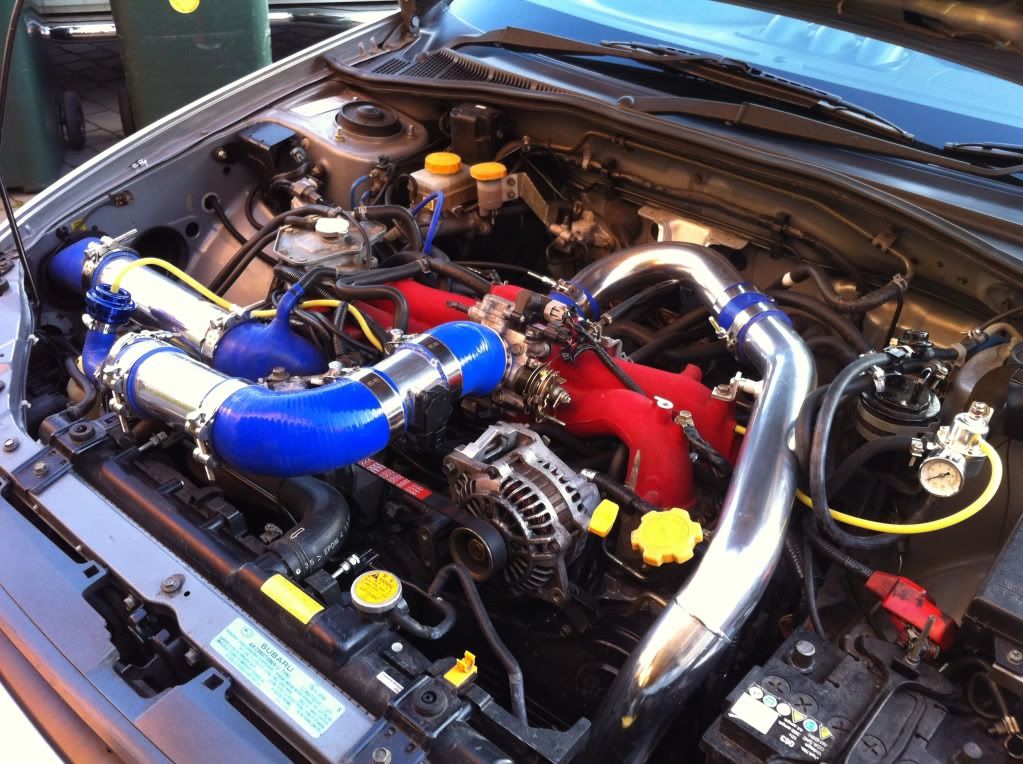
Nice effort mate. Got mine done years ago so is a bit tatty now but heres a pic

You can reroute your throttle cable under the manifold as is and it works. You just need to move the throttle cable outer bracket to a bolt hole on the block right underneath the manifold. Check your clearance on your power stearing pump reservoir as mine fouled by a couple of mm until i took a hammer to it and did a bit of reshaping lol. The is also a small tang on the throttle body where the cable inner sits and that needs snaping off as it gets in the way now you are pulling the throttle at a slightly different angle. It will make sence when you get to it.

You can reroute your throttle cable under the manifold as is and it works. You just need to move the throttle cable outer bracket to a bolt hole on the block right underneath the manifold. Check your clearance on your power stearing pump reservoir as mine fouled by a couple of mm until i took a hammer to it and did a bit of reshaping lol. The is also a small tang on the throttle body where the cable inner sits and that needs snaping off as it gets in the way now you are pulling the throttle at a slightly different angle. It will make sence when you get to it.
#6
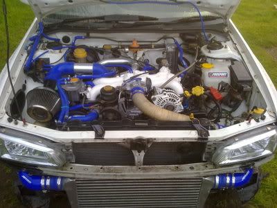
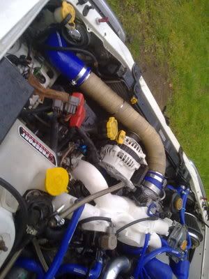
well got few hours on it today, fully built inlet up and fitted and refitted power steering pump which created a problem as the big throttle linkage caught the resevoir but sorted that will take a pic tomorrow and explain what i did. also got the alternotor fitted and a rough mock up of the boost pipes although this will change when the intercooler is flipped.
this is where i'm at
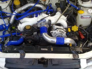
this is where i'm at

Trending Topics
#15
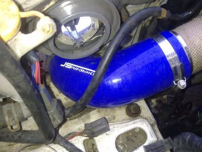
hoses are 63mm internal and i used
http://www.jsperformance.co.uk/
tell shane eric said to contact him and he'll look after you. or let me know what ya need and ill sort them for ya
http://www.jsperformance.co.uk/
tell shane eric said to contact him and he'll look after you. or let me know what ya need and ill sort them for ya
#18
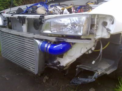
yes im sure it used to come from turbo through inner wing down and round front then from intercooler round underneath then up side of radiator then round the back of engine. intercooler is 40cm high so thats 80cm if it was just straight down let alone the run round back of engine. ill post a pic of all the pipe left. was 40 for welding
#21
https://www.scoobynet.com/general-te...lockwises.html
post 15
quote "and got the pipe work down from nearly 15ft long to under 5ft"
post 15
quote "and got the pipe work down from nearly 15ft long to under 5ft"
#22
Unmapped 12.4s @ 105
iTrader: (29)
Joined: Apr 2005
Posts: 11,777
Likes: 4
From: Newcastle. 330bhp-289lb/ft @ 1bar boost - 12.4s @ 105mph
https://www.scoobynet.com/general-te...lockwises.html
post 15
quote "and got the pipe work down from nearly 15ft long to under 5ft"
post 15
quote "and got the pipe work down from nearly 15ft long to under 5ft"
No mention of that in that post.
Post number 10, maybe.

It's very hard to see your pipe run from the turbo, from your rather small pictures. I'd assumed you'd left that side standard.
Thanks for letting me know how much the welding cost, it's given me a guide price for when I get mine done.

#25
You have went to a lot of trouble rotating the manifold and shortening the pipework into the throttle body and then added length on the outlet side of the compressor. You would have been better using a newage power steering pump and relocating the resevoir to just in front of the drivers headlight, adjusting your filter position slightly and then taking compressor outlet pipe under the manifold and under the headlight. There are loads of pics on my project thread showing how I done it if that helps.
#26
You have went to a lot of trouble rotating the manifold and shortening the pipework into the throttle body and then added length on the outlet side of the compressor. You would have been better using a newage power steering pump and relocating the resevoir to just in front of the drivers headlight, adjusting your filter position slightly and then taking compressor outlet pipe under the manifold and under the headlight. There are loads of pics on my project thread showing how I done it if that helps.

that will be addressed once new turbo fitted
Thread
Thread Starter
Forum
Replies
Last Post
Mattybr5@MB Developments
Full Cars Breaking For Spares
28
29 December 2015 12:07 AM


