
Classic digital climate control
 17 June 2012, 11:23 PM
#1
Scooby Regular
Thread Starter
iTrader: (1)
Join Date: May 2006
Location: Cas Vegas
Posts: 7,833
Likes: 0
Received 0 Likes
on
0 Posts
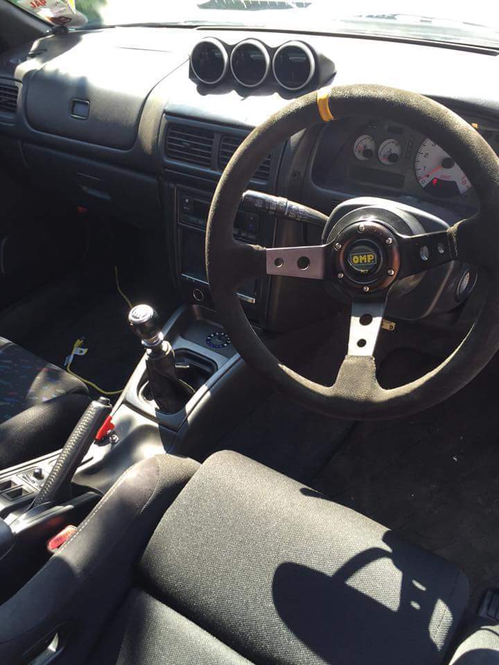
As above I have a version 5 Type R with the **** type climate control and have acquired a digital display from a JDM Forester. The unit fits in place of the old unit and has the same connectors, but when you plug it in nothing happens. I'm presuming that the wiring is different, does anyone know what I need to change to make it fit?
Cheers in advance
Cheers in advance

 thank you
29 June 2012, 07:29 AM
thank you
29 June 2012, 07:29 AM
#6
Scooby Regular
Thread Starter
iTrader: (1)
Join Date: May 2006
Location: Cas Vegas
Posts: 7,833
Likes: 0
Received 0 Likes
on
0 Posts
Think it will be a couple of weeks now till I have a go at it as I'm in the middle of moving house. What hose did you use to connect to the matrix?
Cheers
Cheers
29 June 2012, 08:58 AM
#7
Scooby Regular

Join Date: Aug 2007
Location: Kettering
Posts: 119
Likes: 0
Received 0 Likes
on
0 Posts
Do you mean the cabin temp sensor? There's a pipe that goes to the left of the speedo cowling, remove the speedo surround and you'll see it. Pull the pipe off and extend with a piece of rubber hose.
Thanks Ryan
Thanks Ryan
Trending Topics


 22 August 2012, 11:09 PM
#17
Scooby Regular
Thread Starter
iTrader: (1)
Join Date: May 2006
Location: Cas Vegas
Posts: 7,833
Likes: 0
Received 0 Likes
on
0 Posts
 05 July 2015, 03:16 PM
#20
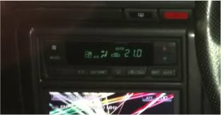
I sold my car and 6 months later ended up buying ronjeramys car with the digital climate control fitted too
Bit of googling and I found this
http://ozfoz.com/forum/viewtopic.php...&sd=a&start=80

Bit of googling and I found this
http://ozfoz.com/forum/viewtopic.php...&sd=a&start=80
 08 October 2015, 10:17 PM
#26
I've looked at that thread and can see the numbers for the pins + colours but not sure what that actually means.
I have a digital panel that came out of a v4 type r, and the seller sent me the wiring plugs to go with it, but the colours are completely different to the ones on my standard 99 panel.
Is it just a couple of wires that need changing or more to it than that? If someone could pm me with a how to it would help as im finding a lot of the threads/post online have missing pics and are difficult to follow
26 April 2016, 11:31 PM
#27
Scooby Regular
iTrader: (4)
Join Date: Sep 2007
Location: JDM MY97 Type R - 2.1 Stroker
Posts: 1,008
Likes: 0
Received 0 Likes
on
0 Posts
I was looking to do this, but sadly the site that had the detailed information was no longer avaialbe.
But fear not! Thanks to the wayback machine, I have managed to get an archived copy of the post with all of the details.
All credit to original thread starter on the other forum, rexnet.com.au
--------
I have been asked a few times todo a DIY on how to install this
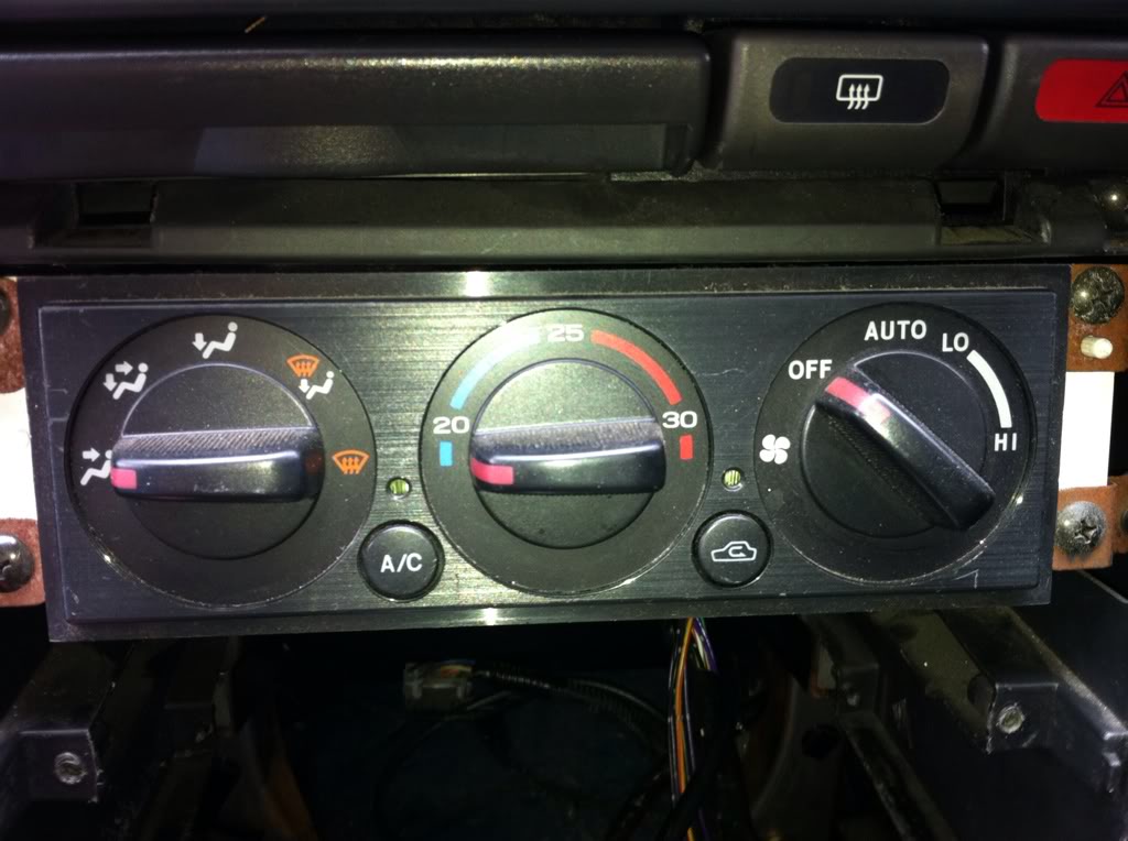
into a GC8 STI V5 & V6. Now before people ask you can NOT to this to a normal WRX as the STI's are installed with climate control air con to begin with. You must have these controls in your car for this to work.
Now before you start you must do this first, as i found out the hard way there are wires in there that will turn the ignition on.
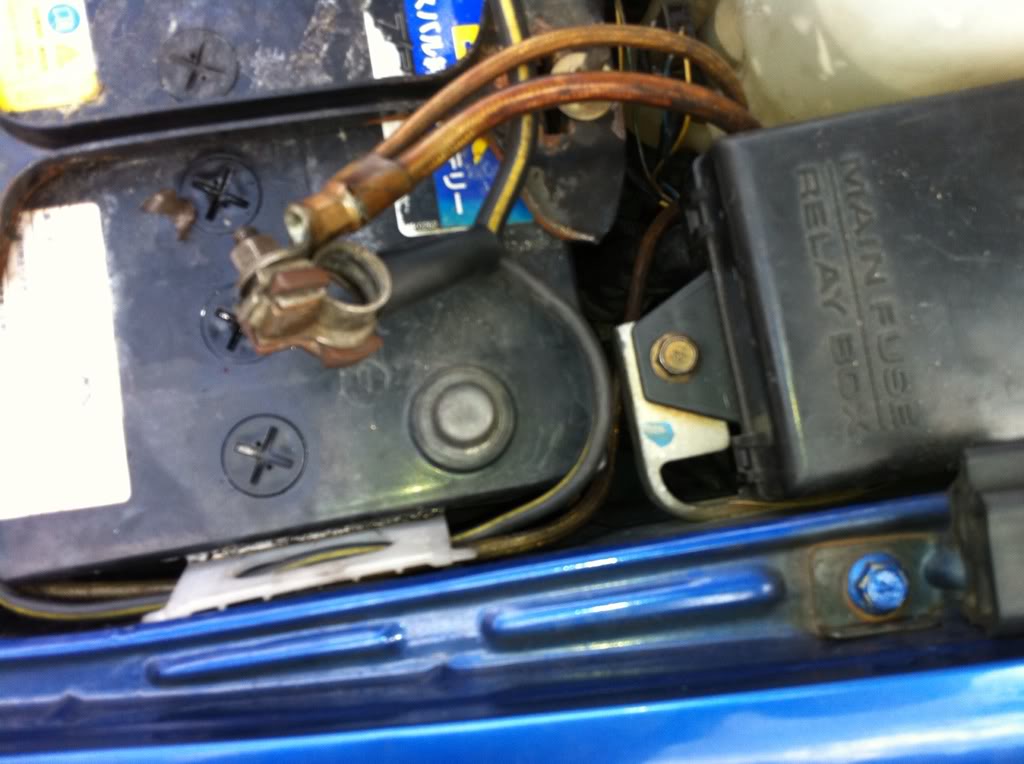
Now I haven't got pictures of how to remove the stereo surround and take the stereo out, but its all pretty simply, a few screws here a few yanks there and you should have something like this
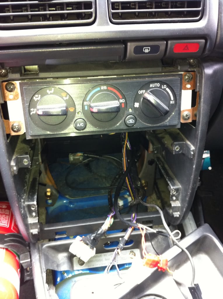
There are four screws holding in the air con controls then all you do is drop it down and unplug the two connectors at the back.
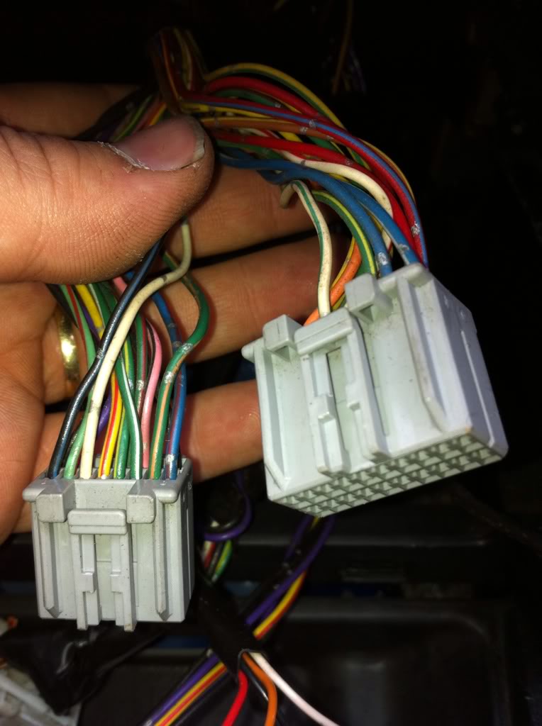
Now you have to start removing the wires out of the back of the plug. There is a little white piece of plastic on the back of the plug.
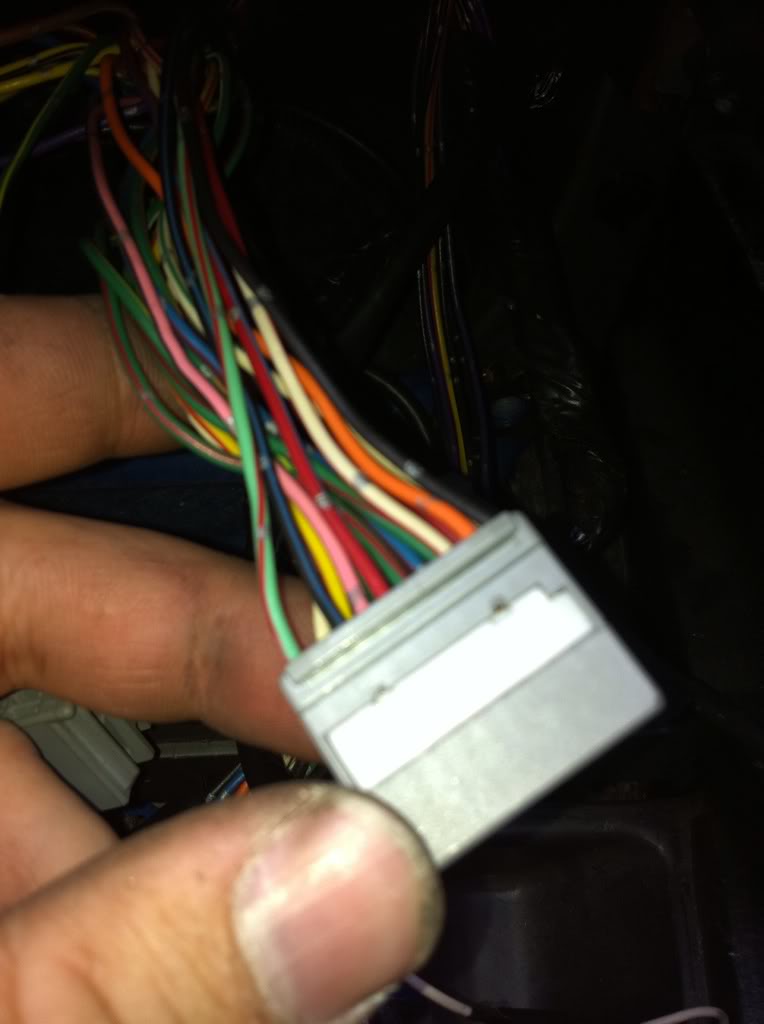
Using a REALLY small flat blade screw driver gently lift the white piece up on the back of the two connectors. Do not remove it, it only lifts up around 3mm. Should look like this.
The easiest way i found to remove the plugs is to just give the wire a good yank and it will come right out.(Please read next step before you start yanking) It is clipped in the plug some how but i could work out how to remove them and the little white piece of plastic that you just lifted holds them into place as well.
Now there are three sets of wires that have the same colours, green/yellow, green/red and black wires. Go ahead and remove all but the GREEN/YELLOW, GREEN/RED. These will be removed but they need to be put into the right position when you remove them from the plug.
After you remove all but the four wires you should have this.
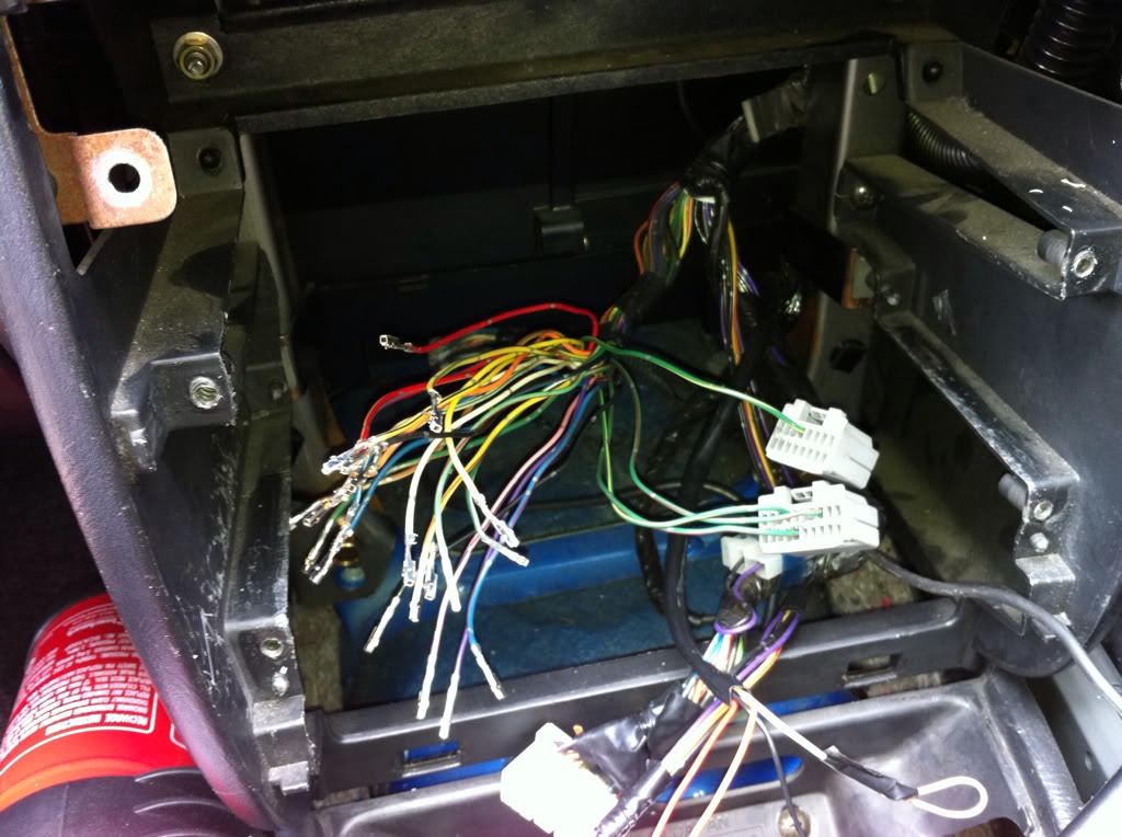
(note i took this photo after I changed around the four wires)
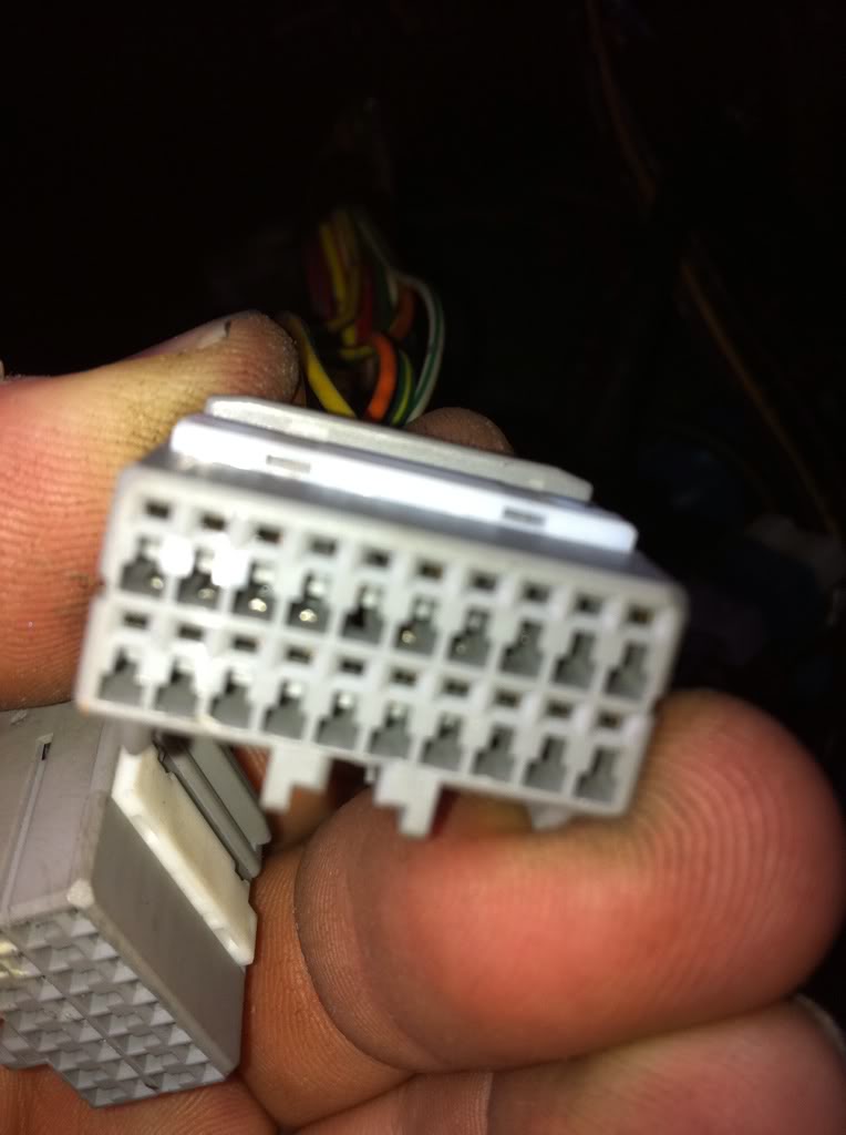
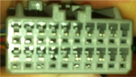
Ok now these are the two connectors i have taken a front photo of them and have given each pin a number. The way you read the number is from left to right. So the first pin(top left) on each plug is pin one and the last pin(second row, last pin on the right) is 16 or 20 dependent on the connector.
Little Connector
Top Row 1 - 8
Bottom Row 9 - 16
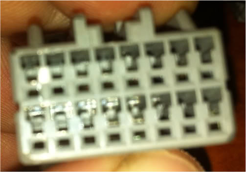
Big Connector
Top Row 1 - 10
Bottom Row 11 - 20
Now its time to reconfigure the wires so that these controls will work. I would recommend doing the Green/Yellow and the Green/Red first. As you finish each connector push that white plastic lock tab back down and this will secure each wire into the plugs.
Little Connector
1 - Purple
2 - not used
3 - Brown/Yellow
4 - Blue/White
5 - Blue
6 - Not Used
7 - Yellow
8 - Not Used
9 - Not Used
10 - Not Used
11 - Not Used
12 - Red/Yellow
13 - Green/Yellow (Originally Position Big Connector pin 7)
14 - Not Used
15 - Not Used
16 - Yellow/Black
Big Connector
1 - White/Green
2 - Red
3 - Green/Red (Originally from Big Connector pin 3)
4 - Blue/Red
5 - Green/Orange
6 - Green/White
7 - Green/Yellow (Originally from Little Connector pin 5)
8 - Yellow/Red
9 - White
10 - Not Used
11 - Black (there are 2, they are both earths so pick one doesn't matter which one)
12 - Orange
13 - White/Red
14 - Not Used - Green/red (Originally from Little Connector pin 13)
16 - Red/Blue
17 - Pink/Black
18 - Black/Blue
19 - Not Used
20 - Light Green/Red
All i can say from this point is to double check and then to triple check your work. If you happy with what you have done then you should have something similar to this
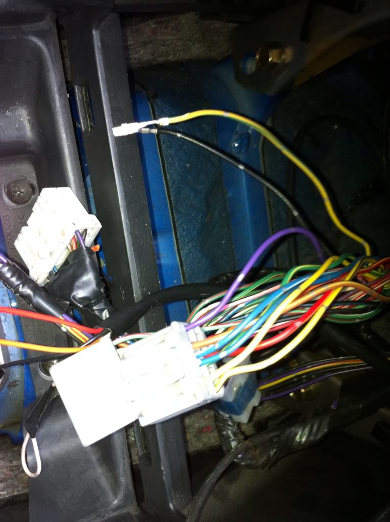
Notice you will have two wires left over. A Yellow/Blue and a Black wire. Tape them up as there not needed anymore. Yellow wire is for the temp sensor under the instrument cluster and the back is just a earth.
On the back of the forester air con controller there is a 1cm round hose nipple there, this does need to be connected to the air con. If you take off the kick panel under the steering wheel, you�ll be able to see where it goes allot easier. If you look up to the blower unit on the drivers side you�ll see a white plastic bit held onto the side of the blower box. It already has a black tube that runs up to the instrument cluster temp sensor. You need to remove that and make your own one up to go to the forester controller. I bought some radiator hose and it seems to work well.
After all of that is done install the controls put the battery back on and test. If its all going fine then reinstall the stereo and put the centre console back together.
Enjoy.
But fear not! Thanks to the wayback machine, I have managed to get an archived copy of the post with all of the details.
All credit to original thread starter on the other forum, rexnet.com.au
--------
I have been asked a few times todo a DIY on how to install this
into a GC8 STI V5 & V6. Now before people ask you can NOT to this to a normal WRX as the STI's are installed with climate control air con to begin with. You must have these controls in your car for this to work.
Now before you start you must do this first, as i found out the hard way there are wires in there that will turn the ignition on.
Now I haven't got pictures of how to remove the stereo surround and take the stereo out, but its all pretty simply, a few screws here a few yanks there and you should have something like this
There are four screws holding in the air con controls then all you do is drop it down and unplug the two connectors at the back.
Now you have to start removing the wires out of the back of the plug. There is a little white piece of plastic on the back of the plug.
Using a REALLY small flat blade screw driver gently lift the white piece up on the back of the two connectors. Do not remove it, it only lifts up around 3mm. Should look like this.
The easiest way i found to remove the plugs is to just give the wire a good yank and it will come right out.(Please read next step before you start yanking) It is clipped in the plug some how but i could work out how to remove them and the little white piece of plastic that you just lifted holds them into place as well.
Now there are three sets of wires that have the same colours, green/yellow, green/red and black wires. Go ahead and remove all but the GREEN/YELLOW, GREEN/RED. These will be removed but they need to be put into the right position when you remove them from the plug.
After you remove all but the four wires you should have this.
(note i took this photo after I changed around the four wires)
Ok now these are the two connectors i have taken a front photo of them and have given each pin a number. The way you read the number is from left to right. So the first pin(top left) on each plug is pin one and the last pin(second row, last pin on the right) is 16 or 20 dependent on the connector.
Little Connector
Top Row 1 - 8
Bottom Row 9 - 16
Big Connector
Top Row 1 - 10
Bottom Row 11 - 20
Now its time to reconfigure the wires so that these controls will work. I would recommend doing the Green/Yellow and the Green/Red first. As you finish each connector push that white plastic lock tab back down and this will secure each wire into the plugs.
Little Connector
1 - Purple
2 - not used
3 - Brown/Yellow
4 - Blue/White
5 - Blue
6 - Not Used
7 - Yellow
8 - Not Used
9 - Not Used
10 - Not Used
11 - Not Used
12 - Red/Yellow
13 - Green/Yellow (Originally Position Big Connector pin 7)
14 - Not Used
15 - Not Used
16 - Yellow/Black
Big Connector
1 - White/Green
2 - Red
3 - Green/Red (Originally from Big Connector pin 3)
4 - Blue/Red
5 - Green/Orange
6 - Green/White
7 - Green/Yellow (Originally from Little Connector pin 5)
8 - Yellow/Red
9 - White
10 - Not Used
11 - Black (there are 2, they are both earths so pick one doesn't matter which one)
12 - Orange
13 - White/Red
14 - Not Used - Green/red (Originally from Little Connector pin 13)
16 - Red/Blue
17 - Pink/Black
18 - Black/Blue
19 - Not Used
20 - Light Green/Red
All i can say from this point is to double check and then to triple check your work. If you happy with what you have done then you should have something similar to this
Notice you will have two wires left over. A Yellow/Blue and a Black wire. Tape them up as there not needed anymore. Yellow wire is for the temp sensor under the instrument cluster and the back is just a earth.
On the back of the forester air con controller there is a 1cm round hose nipple there, this does need to be connected to the air con. If you take off the kick panel under the steering wheel, you�ll be able to see where it goes allot easier. If you look up to the blower unit on the drivers side you�ll see a white plastic bit held onto the side of the blower box. It already has a black tube that runs up to the instrument cluster temp sensor. You need to remove that and make your own one up to go to the forester controller. I bought some radiator hose and it seems to work well.
After all of that is done install the controls put the battery back on and test. If its all going fine then reinstall the stereo and put the centre console back together.
Enjoy.
27 April 2016, 07:16 AM
#28
Scooby Regular
iTrader: (3)
Join Date: Sep 2004
Location: Essex
Posts: 90
Likes: 0
Received 0 Likes
on
0 Posts
The above wiring is incorrect as you can only get hot air when set to 32 degrees and the flap controls to direct heat don't work.
If you use the following as you increase temperature with it set to auto the flaps will move to direct air to the right areas ie floor hands or screen and increase the speed of fans if needed. I did post this on the Aussie site and several others, if you do it and get stuck send me a PM.
1 of 16 VIOLET or PURPLE
2 of 16 NOT USED
3 of 16 BROWN/YELLOW
4 of 16 BLUE
5 of 16 BLUE/WHITE
6 of 16 NOT USED
7 of 16 YELLOW
8 of 16 NOT USED
9 of 16 NOT USED
10 of 16 NOT USED
11 of 16 NOT USED
12 of 16 RED/YELLOW
13 of 16 GREEN/YELLOW from 7 of 20
14 of 16 NOT USED
15 of 16 NOT USED
16 of 16 YELLOW/BLACK
1 of 20 WHITE/RED
2 of 20 RED
3 of 20 GREEN/RED not moved
4 of 20 BLUE/RED
5 of 20 GREEN/ORANGE
6 of 20 GREEN/WHITE
7 of 20 GREEN/YELLOW from 5 of 16
8 of 20 YELLOW/RED
9 of 20 WHITE
10 of 20 GREEN/RED from 13 of 16
11 of 20 BLACK
12 of 20 ORANGE
13 of 20 WHITE/GREEN
14 of 20 NOT USED
15 of 20 NOT USED
16 of 20 RED/BLUE
17 of 20 PINK/BLACK
18 of 20 BLACK/BLUE
19 of 20 NOT USED
20 of 20 LIGHT GREEN/RED
27 April 2016, 04:44 PM
#29
The above wiring is incorrect as you can only get hot air when set to 32 degrees and the flap controls to direct heat don't work.
If you use the following as you increase temperature with it set to auto the flaps will move to direct air to the right areas ie floor hands or screen and increase the speed of fans if needed. I did post this on the Aussie site and several others, if you do it and get stuck send me a PM.
1 of 16 VIOLET or PURPLE
2 of 16 NOT USED
3 of 16 BROWN/YELLOW
4 of 16 BLUE
5 of 16 BLUE/WHITE
6 of 16 NOT USED
7 of 16 YELLOW
8 of 16 NOT USED
9 of 16 NOT USED
10 of 16 NOT USED
11 of 16 NOT USED
12 of 16 RED/YELLOW
13 of 16 GREEN/YELLOW from 7 of 20
14 of 16 NOT USED
15 of 16 NOT USED
16 of 16 YELLOW/BLACK
1 of 20 WHITE/RED
2 of 20 RED
3 of 20 GREEN/RED not moved
4 of 20 BLUE/RED
5 of 20 GREEN/ORANGE
6 of 20 GREEN/WHITE
7 of 20 GREEN/YELLOW from 5 of 16
8 of 20 YELLOW/RED
9 of 20 WHITE
10 of 20 GREEN/RED from 13 of 16
11 of 20 BLACK
12 of 20 ORANGE
13 of 20 WHITE/GREEN
14 of 20 NOT USED
15 of 20 NOT USED
16 of 20 RED/BLUE
17 of 20 PINK/BLACK
18 of 20 BLACK/BLUE
19 of 20 NOT USED
20 of 20 LIGHT GREEN/RED
If you use the following as you increase temperature with it set to auto the flaps will move to direct air to the right areas ie floor hands or screen and increase the speed of fans if needed. I did post this on the Aussie site and several others, if you do it and get stuck send me a PM.
1 of 16 VIOLET or PURPLE
2 of 16 NOT USED
3 of 16 BROWN/YELLOW
4 of 16 BLUE
5 of 16 BLUE/WHITE
6 of 16 NOT USED
7 of 16 YELLOW
8 of 16 NOT USED
9 of 16 NOT USED
10 of 16 NOT USED
11 of 16 NOT USED
12 of 16 RED/YELLOW
13 of 16 GREEN/YELLOW from 7 of 20
14 of 16 NOT USED
15 of 16 NOT USED
16 of 16 YELLOW/BLACK
1 of 20 WHITE/RED
2 of 20 RED
3 of 20 GREEN/RED not moved
4 of 20 BLUE/RED
5 of 20 GREEN/ORANGE
6 of 20 GREEN/WHITE
7 of 20 GREEN/YELLOW from 5 of 16
8 of 20 YELLOW/RED
9 of 20 WHITE
10 of 20 GREEN/RED from 13 of 16
11 of 20 BLACK
12 of 20 ORANGE
13 of 20 WHITE/GREEN
14 of 20 NOT USED
15 of 20 NOT USED
16 of 20 RED/BLUE
17 of 20 PINK/BLACK
18 of 20 BLACK/BLUE
19 of 20 NOT USED
20 of 20 LIGHT GREEN/RED
Heaters work only on hot, on windscreen only and low/high.
Other functions don't work.
09 February 2019, 08:13 PM
#30
Scooby Regular

Join Date: Mar 2011
Location: aylesbury
Posts: 37
Likes: 0
Received 0 Likes
on
0 Posts
(i know its an old thread,. and its probably not known, but i'll ask anyway,)
does anyone know how to convert a uk2000 slider type controls to the climate control above?
i want to convert the slider controls and will get the parts from someone breaking an STI with climate control,. but i am not sure what bits i will need to buy,. is it just the heater matrix, control unit and a wiring pigtail? or does it require full wiring loom,. maybe other parts i have not thought of?
i am stripping my car back to a bare shell and relocating the fuse box (going for a clean engine bay look) so i don't mind if its alot of work,. but i just need to know what parts i will need to buy from an STI before i start the rebuilding of the wiring loom / interior etc.
thanks