Anyone good with electrical circuits?
 10 December 2008, 08:29 PM
#1
Scooby Regular
Thread Starter
iTrader: (21)
Join Date: Oct 2008
Location: Whitby, North Yorkshire
Posts: 3,016
Likes: 0
Received 0 Likes
on
0 Posts
I'm struggling with adding a timer to a machine we have at work. We need it adding as the machine keeps knackering the motor and contactors due it it flicking on and off every few seconds....and it shouldn't be doing this.
So we want to add a timer, so when the the ultra-sonic level sensor flicks 'off' it sets a timer going for say 5minutes, so what ever the sensor then wants to do within this 5minutes it can't!
But after the 5minutes the machine will run 'on' as we know the level will have dropped enough, so the machine will run ok until it gets full again.
It's because when the hopper which is getting filled is nearly full, the crappy sensors can't figure out if its full or not for ages. They are ok when the hopper is empty, they fill nicely!
Does anyone understand what I mean?
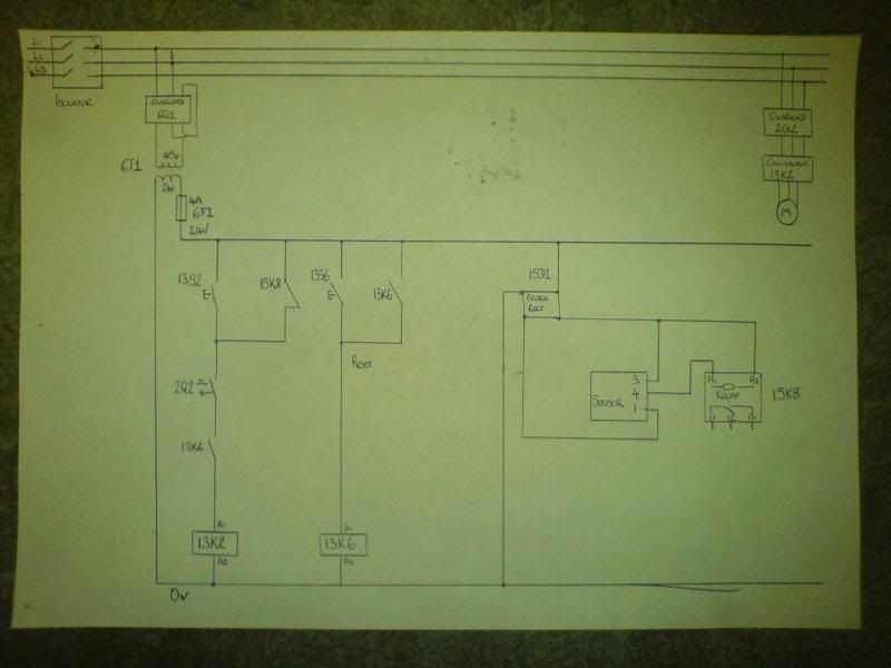
We dont have circuit diagrams as the bloke who use to do all this work didnt ever draw them, and has now left. The control box is a mess as well. I have drawn a circuit diagram the best I can so can post a picture of this (via a camera) if anyone thinks they could maybe help. It probably will be really simple, but I'm tired and cant seem to work anything out tonight.
I'm sure a simple timer is all it needs, with a normally open/close contact, and a coil which activates when it needs to (A1/A2). The sensor has 3 wires going to it, which is a 24vDC an 0V, and the 'control' wire which completes the coil (A1/A2) of a relay depending if it is 'sensing' or not.
Thanks
So we want to add a timer, so when the the ultra-sonic level sensor flicks 'off' it sets a timer going for say 5minutes, so what ever the sensor then wants to do within this 5minutes it can't!
But after the 5minutes the machine will run 'on' as we know the level will have dropped enough, so the machine will run ok until it gets full again.
It's because when the hopper which is getting filled is nearly full, the crappy sensors can't figure out if its full or not for ages. They are ok when the hopper is empty, they fill nicely!
Does anyone understand what I mean?
We dont have circuit diagrams as the bloke who use to do all this work didnt ever draw them, and has now left. The control box is a mess as well. I have drawn a circuit diagram the best I can so can post a picture of this (via a camera) if anyone thinks they could maybe help. It probably will be really simple, but I'm tired and cant seem to work anything out tonight.
I'm sure a simple timer is all it needs, with a normally open/close contact, and a coil which activates when it needs to (A1/A2). The sensor has 3 wires going to it, which is a 24vDC an 0V, and the 'control' wire which completes the coil (A1/A2) of a relay depending if it is 'sensing' or not.
Thanks
 10 December 2008, 10:10 PM
#2
Scooby Regular
What you've described is known as hunting, and it's common practice to use a timer to overcome it when controlling the fill of a vessel using only one level sensor. Your former controls guy sounds like the sort of cowboy who burns factories down 
On the systems we build at work, we tend to get round this problem by using two sensors; a low level to start the fill, and a high level to stop it
On the systems we build at work, we tend to get round this problem by using two sensors; a low level to start the fill, and a high level to stop it
10 December 2008, 10:17 PM
#3
Scooby Regular
Sorry I forgot to tell you where to put the timer ")
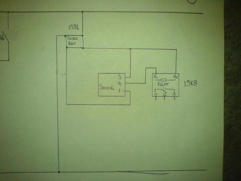
You need to connect the timer coil into the 'signal' wire from the sensor, connect the motor contactor to the timed contacts.
If you want to PM your wiring diagram to me, I can get one of the guys at work to draw in exactly what you need to do.
You need to connect the timer coil into the 'signal' wire from the sensor, connect the motor contactor to the timed contacts.
If you want to PM your wiring diagram to me, I can get one of the guys at work to draw in exactly what you need to do.
10 December 2008, 10:40 PM
#4
Scooby Regular
Thread Starter
iTrader: (21)
Join Date: Oct 2008
Location: Whitby, North Yorkshire
Posts: 3,016
Likes: 0
Received 0 Likes
on
0 Posts
Yeah, he was a TOTAL cowboy. Were finding a lot of his 'work' now. If I'm honest none of us are that good with stuff like this, and I'm just a year out of my apprenticeship so am still learning, and teaching myself most the time.
We did use to have two sensors on the original machine, but as things changed they didn't do the job so we were recommended to use ultrasonic ones. But now we have the problem of going through contactors on motors! lol.
This is what I've drawn from the panel (it may not be 100%) but its the 'Sensor' 4 cable and the 15K8 Relay which I think I need to look at.

Thanks a lot!
Chris
We did use to have two sensors on the original machine, but as things changed they didn't do the job so we were recommended to use ultrasonic ones. But now we have the problem of going through contactors on motors! lol.
This is what I've drawn from the panel (it may not be 100%) but its the 'Sensor' 4 cable and the 15K8 Relay which I think I need to look at.
Thanks a lot!
Chris
11 December 2008, 12:49 AM
#5
Scooby Regular

 11 December 2008, 11:02 AM
#6
Scooby Regular
Thread Starter
iTrader: (21)
Join Date: Oct 2008
Location: Whitby, North Yorkshire
Posts: 3,016
Likes: 0
Received 0 Likes
on
0 Posts
I'm going to rewire it once I get the diagram sorted. I'm quite good at building circuits, just not designing and modifying them, lol.

Thread
Thread Starter
Forum
Replies
Last Post
Scott@ScoobySpares
Full Cars Breaking For Spares
61
11 January 2021 03:08 PM
Scott@ScoobySpares
Full Cars Breaking For Spares
7
14 December 2015 08:16 AM